

Fuel Jettisoning SIMulation (FJSIM) for Prediction of Groundfall
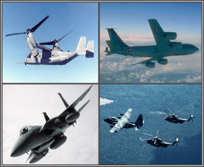
Fuel jettisoned from aircraft in flight may pose a health and environmental hazard at the surface. The fuel jettisoning simulation model FJSIM provides a key tool for evaluating the health and environmental impact of fuel jettisoning events from fixed and rotary wing aircraft. Military pilots are sometimes required to jettison fuel to land safely. The U.S. Air Force conversion from JP-4 jet fuel to the less-volatile JP-8 in the 1990s substantially increases the chances of significant JP-8 groundfall from jettisoned fuel. Realizing this, the Air Force embarked on the FJSIM research effort to accurately predict surface concentrations of JP-8 in order to protect people and resources on the ground. FJSIM combines a detailed, experimentally-verified fuel evaporation model, ambient meteorological conditions and individual aircraft characteristics to yield a demonstrator model for fuel jettisoning. This Windows-based model lets users estimate the location, total mass, volume, and areal extent of the groundfall from actual jettison events and planned operations, and can assist in reviewing and developing fuel jettison policies.
The principal components of the FJSIM model are:
- Multi-component evaporation
- Parameterized atmospheric meteorology
- Modeled aircraft wake characteristics
- Experimentally determined drop size distribution
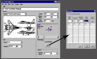
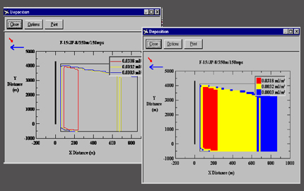
The model features numerous input/output elements and displays. A main screen (Figure 2) contains nearly all U.S. Air Force aircraft, and other aircraft can be easily added. Plots of surface deposition are available and provide the approximate location, areal extent, and concentrations of material reaching the ground (Figure 3). Separate plots of drop size distribution and time aloft are also provided, as is surface evaporation (a result which answers “How long will the fuel remain on the surface”).
The technical basis of FJSIM is summarized in:
- Quackenbush, Teske, and Polymeropoulos “A Model for Assessing Fuel Jettisoning Effects”, Atmospheric Environment, Vol. 28, No. 16, pp. 2751-2759, 1994.
Other references:
- Teske, M. E., A. E. Kaufman and C. E. Polymeropoulos, “Dropsize Distribution from Large Orifices,” ILASS-Americas 9th Annual Conference on San Francisco, CA, pp. 268-272, 1996.Liquid Atomization and Spray Systems
- Runge, T. H., Teske, M. E., & Polymeropoulos, C. E. (1998). Low-temperature vaporization of JP-4 and JP-8 fuel droplets. Atomization and Sprays, 8(1), 25-44.
- Teske, M. E., Thistle, H. W., & Ice, G. G. (2003). Technical advances in modeling aerially applied sprays. Transactions of the ASAE, 46(4), 985-996.
- Teske, M. E., Thistle, H. W., & Londergan, R. J. (2011). Modification of droplet evaporation in the simulation of fine droplet motion using AGDISP. Transactions of the ASABE, 54(2), 417-421.
- Teske, M. E., Thistle, H. W., & Fritz, B. (2019). Modeling aerially applied sprays: An update to AGDISP model development. Transactions of the ASABE, 62(2), 343-354.
Mount Rose Scientific, LLC acquired all rights to FJSIM from Continuum Dynamics, Inc.
Contact Us for more information or to arrange for licensing FJSIM.